

Material Mixing and Layering Systems in Octane:
Cinema 4D Stepthrough
Cinema 4D Stepthrough
This is meant to be a companion piece for the Mixing and Layering Systems in Octane: Technical Deep Dive guide.
This writeup is a step-by-step walkthrough that takes you through several strategies when choosing how to mix and layer materials and textures. The Deep Dive covers each type in more detail.
There is also a version of this document for Octane Standalone in case it’s closer to the DCC you’re using.
Octane has several ways of layering textures and materials together to form complex looks. This guide will walk you through how to use the most common ones by texturing a sci-fi crate.
There’s a lot of overlap and many ways to accomplish the same task in Octane. The goal of this stepthrough is to introduce you to as many layering and mixing systems in Octane as possible over the course of one project and then let you decide which ones you think will work the best in any future projects you make.
A note about nodes: A lot of the layering and mixing systems in Octane can get pretty complex, so we’ll be focusing on using the Octane Node Editor rather than the standard C4D Material Editor workflow. If you’re new to nodes, it may seem a little overwhelming at first, but it actually becomes easier to visually map out an entire system if you can see the whole thing at once rather than bouncing back and forth between levels.
Overview
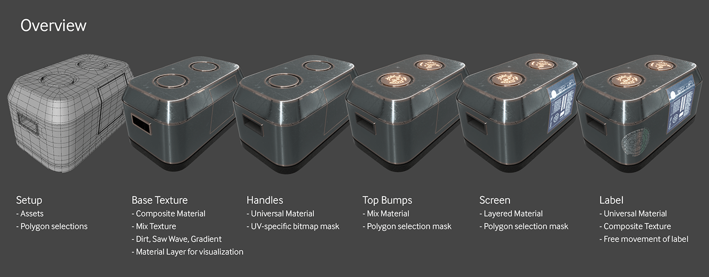
This is a long and complex guide, so to help you get the 20,000 foot view, we’re just going to quickly go over what we’re going to do and what we’ll cover.
Setup
We’ll talk about how the C4D file is constructed and point out where the assets originate from.
Base Texture
We’ll build a Composite Material and set up a procedural mask using a Saw Wave, Gradient and Mix Texture node to tell Octane where to apply two different scratch masks. We'll take a look at the Add Node, and also be using a Dirt Node to apply some edge wear. We’ll also touching on grouping nodes to clean up the node graph. Finally we’ll reuse our procedural mask to restrict a rubber material to the bottom.
Masking Strategies
In this section we’ll touch on UV mapping, polygon selections, and UV map-specific bitmap masks to discuss how to apply different masks to the various parts of the model.
Handles
Here we’ll be using a Universal Material with a UV-specific bitmap mask in the opacity channel to apply a rubber material just to the handle areas of the crate.
Top Bumps
We’ll use two Mix Materials to show off how that system works and why it’s still relevant in Octane for Cinema 4D. We’ll use polygon selections here to mask off the areas of the crate we want these materials to appear in.
Screen
We’ll have a look at the Layered Material and how Material Layers work for the screen. The masking here will be done with polygon selections.
The Label
The label will also be a Universal Material with an Alpha channel, but it’ll make use of the new Composite Texture node to add and subtract portions of the mask.
Setup
We’ll need some assets to get started. These come from HDRI Haven, CC0 Textures, JSplacement, and the rest are custom assets built from scratch for this tutorial.
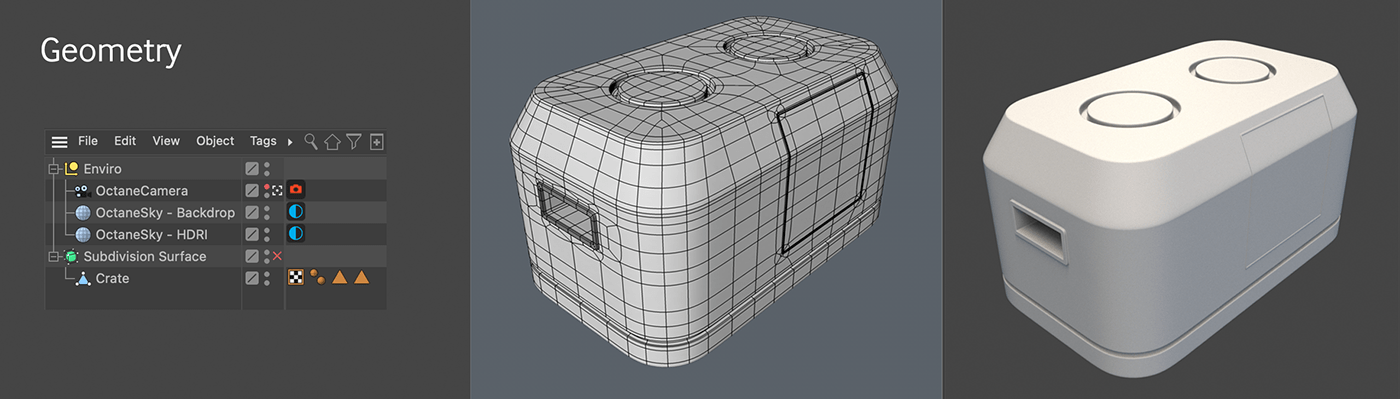
Geometry
For this exercise, we’re going to use a fairly simple sci-fi crate mesh. This crate was modeled using subdivision surfaces techniques so that the UV mapping is easier to understand.
The scene has the Adams Place Bridge HDRI from hdrihaven.com (desaturated) for reflections, and the backplate is overridden by a neutral gray color so it’s not distracting.
It also has three polygon selections (the little triangle tags on the Crate mesh) - one for each of the cylindrical bumps on the top, and one for the screen. We’ll be using those to restrict materials to just those areas.
The Base Texture
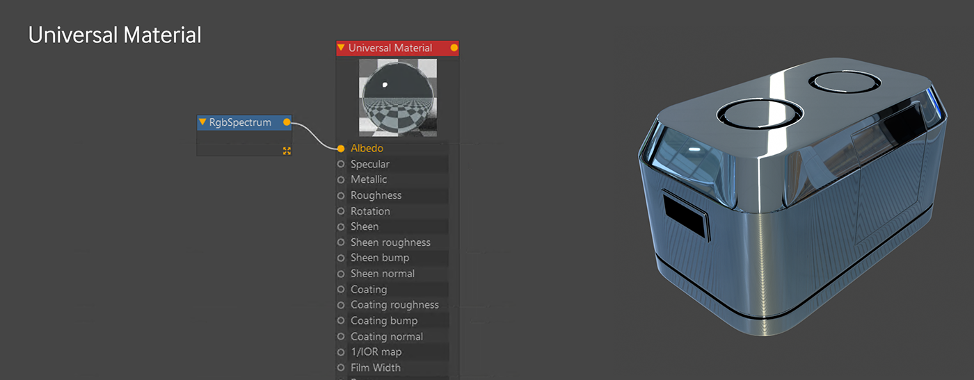
We’re going to start simple with a Universal Material (the material of champions™). There’s an entire writeup on this material if you want to learn more about it.
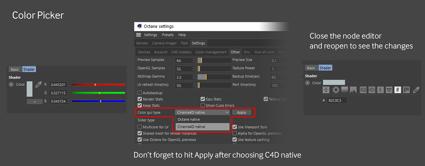
Let’s give it a nice medium steely blue color like #B2C0C3. Rather than embed this value, let’s use an external RGB Spectrum node so we can change it or mix it later. In C4D the color picker defaults to Octane’s 0-1 RGB system. If you click the little white square (the color preview) you can get access to HSV, Hex, etc, or you can choose a default color picker in the settings.
Building a Saw Wave Mask
Next up we’re going to add some scratches to this thing to rough it up and make it look used. This crate will probably see more damage on the sides and bottom than the top, so we’re going to use two different scratch maps - light scratches for the top and heavy ones for the rest. Both will get fed into the roughness channel via a Mix Texture node, but we need a way to specify which part of the mesh gets one texture and which gets the other. For this, we need a mask.
This is going to be a pretty simple mask, so rather than worrying about mapping to UVs or anything complex like that, we’re going to build a procedural setup that allows us to control where each texture shows up based on a gradient.
The seemingly obvious thing would be to use a Gradient node, but that’s one of those things that trips up beginning users of Octane. It’s not a standalone node that generates color data like one would expect coming from the 2D art world. It’s more like a remapping tool similar to a Levels or Colorizer effect. It needs a texture input to be able to do anything useful.
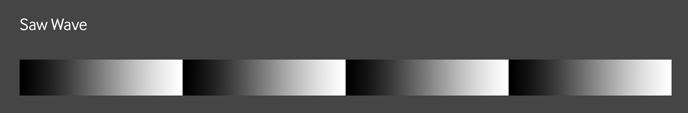
So what we’ll really start with instead is a Sine Wave texture node set to Saw Wave. Sine/Saw Waves do generate color data, and while a sine wave oscillates between 0 and 1 (white and black), a saw wave goes 0-1, then immediately starts over at 0, giving a great visual indicator of where the gradient starts and ends.
If we just run the Sine Wave node into a Gradient node and put it into the Roughness channel of our material (where it’ll eventually end up), it’ll be annoying to try to visualize what’s going to happen. What we need is some way to just see the effects of the gradient on the material without having to disconnect any nodes or change any parameters.
Sidebar: Visualization
Fortunately there are a few ways to do this. We can right click a node and choose “solo node”. That works well in a large node chain, but sometimes can cause issues in certain channels. The way we’re going to do it here is to use a Diffuse Material Layer.
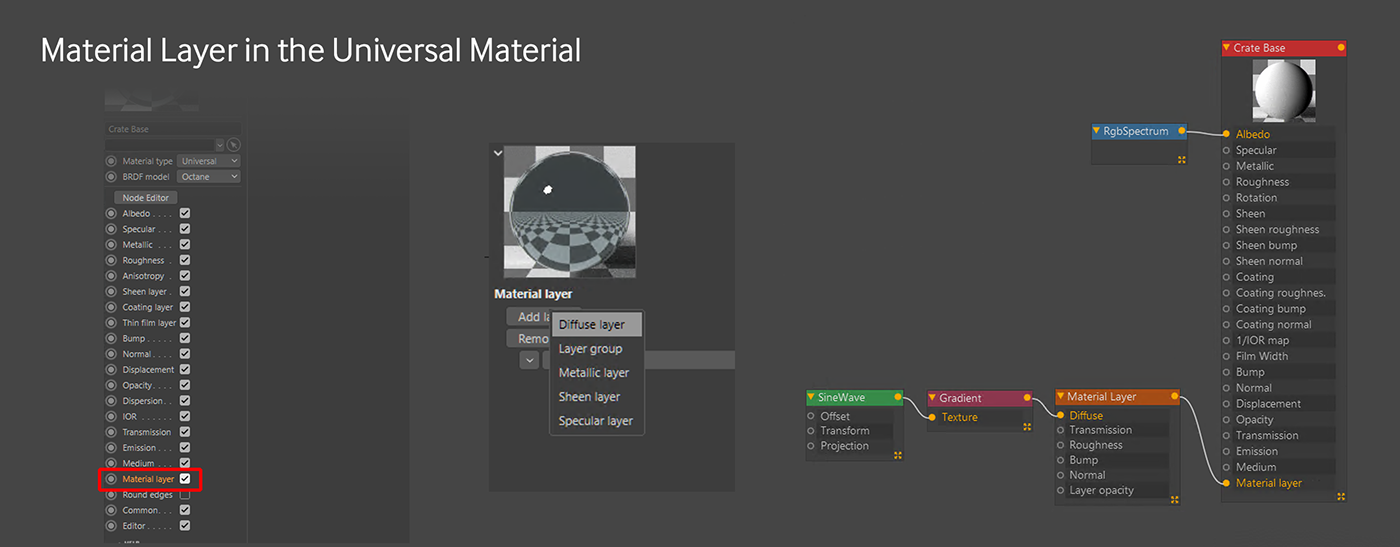
By default, the Material layer is disabled in the Universal Material - we need to go to the Basic tab in the node editor view, or in the Material Editor view it’s just at the bottom of all the checkboxes, and turn it on. Now the input shows up in the node editor. We can either pull a Material Layer off from the side of the node editor interface, or in the Material Layer tab in the Node inspector section of the node editor, choose “Add Layer” and pick “Diffuse layer”. This will override everything in the material and we can plug our Sine Wave->Gradient chain into this and see a black and white representation of the gradient on the mesh. To get back to our original metal material, we just need to disconnect the layer and have it hang out there until we need it again.
Note: The Material Layer input on the Universal Material can only take one layer. If you need more layers, you can set the Material Layer node type to Layer Group and you’ll be able to run seven more layers into that group.
Adjusting the mask
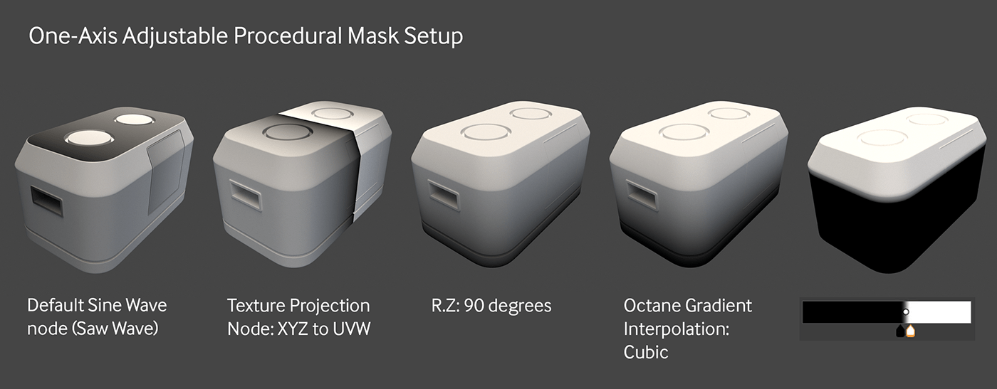
When we add the saw wave to the Diffuse layer, we’ll see some weird results. This is because of the projection type for the texture. The Technical Deep-dive talks about this in depth, but for now we just need to know that most nodes in C4D default to Mesh UV projection (which we’ll use later). What we’re after here is XYZ to UVW projection. This type of projection maps the texture based on the world or object’s XYZ coordinates. This should make sense soon.
To change the projection of a texture, we need to add a Texture Projection node into the Saw Wave node. Now we can set that to XYZ to UVW and the gradient looks a little more like what we’re after, but it’s going in the wrong direction. Not an issue, we can just rotate it 90 degrees on the Z axis in the Texture Projection’s Internal Transform Section. Why Z? Because the X and Y axes didn’t do what we wanted, but Z did. Trial and error is the way to go if you don’t do this a lot :D
So now it’s even closer to what we’re after, but there are still a few steps to go. By default, the Interpolation dropdown in the gradient node is set to Linear. There are technical reasons for this which are out of the scope of this guide, but just know the way to get a smoother black-to-white transition is to change the mode to Cubic. Now it’s a pretty smooth. Finally, we can grab the handles and space them closer together and then move both of them left to right in order to put the gradient line right on the top of the sides before it starts slanting up toward the top. Anything that’s currently black will be texture one, anything that’s currently white will be texture two, and then the small band of grays will blend the two together.
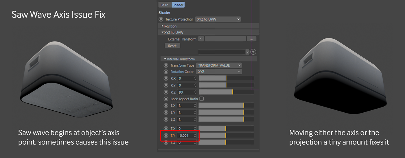
One last thing to be aware of - if we look at the underside of the crate, we’ll see something weird happening. This is because the gradient is zeroing out exactly at the anchor point of the object (which is where the saw wave starts). There are two options to fix this. Either move the anchor point down just a hair, or just put a very slight negative value in the T.Y field in the Internal Transform section of the Texture Projection node. -0.001 should work. And there we go, an adjustable 1-axis quick masking system.
Mix Texture - Setup
Now that we have our mask, we can use a Mix Texture node to put together our scratch maps. This can be achieved with a Composite Texture node as well, but since it’s a simple two-part system, the Mix Texture is faster and a little cleaner for this application. We’ll continue to do this on the Diffuse Layer so we can easily see what’s happening, and then apply it to the roughness channel of our Universal Material once we’re happy with how it looks.
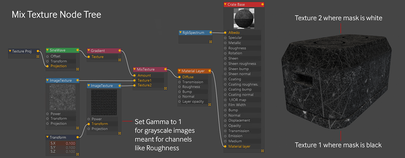
The Texture 1 input gets the really rough scratch map (CC0T Metal01_Roughness.png) so it looks like the sides took more of a beating than the top. Texture 2 gets the less intense one (CC0T Metal01-alt_Roughness.png), and then the mask that we made with the Sawtooth Wave Node which goes from black at the bottom (no contribution) to white at the top (full contribution) means that only the top bit gets the less intense scratching.
There are some other things to be aware of here.
First off, these are grayscale maps meant to go into the roughness channel, which doesn’t accept color data and work in a linear color space. In order to appear properly, the Gamma needs to be set to 1 (ImageTexture gamma defaults to 2.2)
Second, even though the mask we built is in the XYZ to UVW projection, each new ImageTexture node defaults to Mesh UV projection. That’s great here because the model’s UVs are set up pretty well, but if you’re working with a model with bad UVs, the projection will probably have to change. For a boxy model like this, if the UVs were bad, either Triplanar or Box projection would probably be the best bet.
Lastly, the top scratches texture came in way too large - piping in a Transform node and setting the scale to 0.1 made it look better.
Mix Texture - Applying to Roughness
Let’s disconnect our Diffuse layer from the Material Layer input. If we were to just disconnect the Mix Texture from the Diffuse layer and keep it plugged in, it would continue to override the whole material with a white diffuse material. Next up, let’s disconnect the Mix Texture from the Diffuse Layer node (but leave it there in case we need it later), and pipe the Mix Texture into our roughness channel to see what it looks like.
At any point, it might help to rotate the HDRI and/or increase the intensity to get a better idea of what it’s doing on a reflective surface.

Once the texture is applied to the roughness channel, we can see it’s still a bit too shiny. To fix this, we’re going to need to combine the output of our mix texture with white in order to brighten the whole texture up. The way we’re going to do this is with an Add node. This node blends together two textures using the Add blend mode, which will bring all of the values closer to 1 (white) and increase the roughness.
The Add node is super simple, and only has two inputs. We need to run our whole tree from the Mix Texture back into the Texture 1 input, and then run another texture into the Texture 2 input to brighten it all up. We can use an RGB Spectrum node for this and start at white.
Once we insert the Add node and white RGB Spectrum, we’ll see that we lost all the detail in the crate. The Add blend mode works by looking at the values of both textures and adding them together. If a pixel of texture 1 is 128 (medium gray) and the corresponding pixel of texture 2 is also 128, the add node combines them to be 256 (well, 255 which is the max), or pure white. Since the white RGB spectrum is already at 255 across the board, every pixel is already maxed out and the whole combined image is white, or 100% rough. To see any detail, we need to drag the gray value of the RGB spectrum way down.
This is easy to do in HSV mode, just drag the V (value) slider. We only need the image a bit lighter to add some overall roughness, so something like V=20% will work.

Convert to Composite Material
To make the crate look a little more beaten up, we’re going to put some wearing around the edges. This can be achieved with material layers, but it would also be a good opportunity to show off the composite material and the conversion process, so let’s do that.
Let’s make a new Composite Material - it’s located in the Octane Live Viewer window under Materials, and apply the composite material to our mesh.
Important: As of the current version at this time (2020.2.1), the Composite Material requires submaterials to be used rather than standard Octane materials. We can either pull a Submaterial off the left hand side of the node editor, or we can go into the Material 1 tab of the Composite Material in the node inspector and hit the Add Material button there. Either way, this will create a Glossy submaterial. We can then change this to a Universal Material (or almost any other type of material) in the Basic tab of the submaterial in the node inspector.
A third way of creating a submaterial, which is what we’re going to do now, is convert our already constructed blue metal material into a submaterial. Let’s get the node editor open for the new composite material we just made, and drag the metallic base material we already have from the material manager into the node graph. What we just did right now was create a link to the original material. This means if we change anything, like say change the albedo to green, it will update the original material as well, so be careful.
If we try to hook that material up to the composite material node, we’ll see it doesn’t work.

What we need to do here is right-click the material and choose “Convert to sub_material”. A copy of the material will appear, but at the top, the copy will say “Sub material”. This copy is no longer a link - whatever is changed here won’t affect the original material.
Depending on the version of Octane you’re on, a few things might happen. In earlier versions, it would convert the material to a Diffuse type submaterial. If this is the case, you’ll need to change it back to a Universal type in the Basic tab of the material and may need to hook some of the nodes back up to the right channels.
You might also still see the original material - DO NOT DELETE THIS - it’s still a live link from the original material and you’ll end up deleting the original material. If this happens, Hit the Get Active Material button in the upper left of the node editor, or just click a different material to get its node graph up, and then click the composite material again and it’ll be gone.
Your new submaterial might be hooked up to the Material 1 input. If so, great, if not, go ahead and do that manually.
It’s also worth noting here that you can’t convert the submaterial back to a regular material. You can, however, copy all the nodes, make a new material of the same type, paste the nodes into the new material’s node graph, and hook them back up to the appropriate channels.
All those caveats out of the way, let’s move on to making some edge wear.
Edge Wear with a Material Layer
The last thing we’re going to do to the base material is add some wear. We’ll do this by adding a Metallic Submaterial and a mask into the Material 2 Mask input.

First off, let’s make a Universal Submaterial. This can be achieved by either clicking the Composite Material, going into the Node Inspector, going to the Material2 tab and hitting Add material, or by dragging Sub material from the list of nodes on the left and connecting it to the Material 2 input in the Composite Material node. If you want to get really fancy, you can also hit spacebar while the node editor is active or shift-C, and search for “sub material”.
When we hook it up, we’ll notice nothing happens. By default, the mask for that material is set to 0 (equivalent to a solid black image), which means it has no effect. To see the new submaterial, let’s set the mask to 1 (equivalent to a solid white image). Eventually we’ll override this with a mask that only affects the edges, but for now we can see what we’re doing when editing our new submaterial.
We then need to convert it to either a Metallic or Universal material. Let’s use a Universal because it would give us more options in the future if we wanted to refine the material more. We’re going to go for a realistic copper here because hey, why not.

The Universal submaterial is slightly different than the standard Universal Material. The settings for Copper here are Albedo=black, Specular=0, Metallic=1. Index = RGB IOR. The values under RGB IOR are as follows: Metallic IOR: 0.21845, 3.637. Metallic IOR (green): 0.94313, 2.5944. Metallic IOR(blue): 1.1654, 2.3896. Everything else is default. Where did those numbers come from? In the Universal Material Guide, there’s an in-depth explanation of metallic IOR. It’s super nerdy, but worth knowing if you’re after the most realistic metals possible.
Once again it’s worth rotating the HDRI around to see what the metal will look like in various conditions. In the example above, the Power was set to 1.5, RotX is -0.25, RotY is 0.
Dirt Node Mask
Time to make the mask for the copper wear. The Dirt Texture node allows you to find the edges of a model. We lost our Diffuse Material layer when we did the submaterial conversion because it wasn’t hooked up to anything. While we could just get another one and do the same thing we did before, we’re using a Composite material, so we can just make a new submaterial to test our mask out on. Using any of the methods we used before, let’s make a new submaterial, change the type to Diffuse, and then set the mask value to 1 for Material3.
Sidebar: Cleanup

By now the node graph is starting to look a little busy. Let’s clean it up a bit so we can focus on the submaterial we’re currently working on. The first thing we can do is take everything in Submaterial 1 (the bluish metallic base) and group them all. We can do that by selecting all of the nodes associated with that material, and then right-click any one of those nodes and choosing “Group items”. This will collapse them all into a single node. To expand it back it back out, we can just right-click the group and choose “UnGroup items”.
In the case of the copper material where we don’t have any attached nodes, a quick way to minimize this is to just double-click in the red top portion where the name is and it collapses the node to just that bar. Now we can rearrange them and focus on the mask.
Back to the Dirt Node Mask

Time to pipe in a Dirt texture into the Diffuse channel of the Diffuse material. This is the same as the Albedo channel in the Universal Material if you decided to go that route.
There are a bunch of parameters to play with here, but the most important one for a mask like this is “Invert Normals”. That will amplify the effect of the edge wear. Once that’s checked, we can play with the Radius, Strength, Spread, Details and Bias to get the Mask looking how we want.
Since this is a mask for Material 2 (the copper material), the white shows where the copper will be. Right now it’s mostly white, with some black edges. We want the opposite of this - the copper should appear on the worn edges, so we’ll need to invert the mask. Pretty easy to do - just run the dirt texture node through an Invert node.

Important: When it comes time to use our dirt setup as a mask, it’s important to know that we can’t just disconnect our diffuse material from the Material 3. The Material3 Mask is still set to 1, so if we disconnected that, the material would still look like a white diffuse material. What we need to do is take the Material3 Mask value down to 0 so we can see the mixed metal materials.
We’re going to leave it there and use it as a rubber bumper material for the bottom.
Rubber material for bottom

The last thing we’ll do is put a rubber-like material at the bottom. We’re going to borrow some nodes from the base material to do this. Let’s bring the Material3 Mask value back up to 1 so we can see what we’re doing.
For the Diffuse (or Albedo if you’re using the Universal Material), let’s set the color to H:0, S:0, V: 15 to get a dark gray.
A rubber material has some sheen to it, so we can either convert our Diffuse Material to a Universal Material and use the Sheen channel, or we can add a sheen Material Layer to our Diffuse material. If you’re using Octane 2020.2.1 or later on Windows, you can go the Material Layer route. In earlier versions of Octane for Windows or in Octane X PR8 or earlier for MacOS, use a Universal Material for this step instead - both ways yield the same results.
Way back in the beginning of this walkthrough, we added a Material Layer to our Universal Material to previsualize the mask. Let’s do the same thing here and go to the Basic tab of the Diffuse material, and turn on the Material Layer channel. Now let’s grab a Material Layer node from the node list on the side and plug it in.
In the Basic tab of the Material Layer in the node inspector, let’s change the Layer type to Sheen layer. Next let’s head over to the Sheen tab and make sure it’s set to white (full effect), and then go to the Sheen Roughness tab and set that to 0.16. If you’re going the Universal Material approach, just change the Sheen to 1 (which is the same as white), and set the Sheen Roughness in that same tab to 0.16.

Next up let’s ungroup our base layer by right clicking the group node we made earlier and choosing UnGroup items. We want the same scratch pattern we used for the base layer on the rubber material, so we’re just going to pull another wire from that Add texture and use it in our new submaterial. Since this is a diffuse material, running it into the roughness channel won’t really do much, so let’s put it into the bump channel instead. When we run it into bump, it looks like there are raised welts on the material. To make them look like gouges instead, let’s use run it through an Invert node so the bump goes the other way.
Rubber Material Mask

Now that we’re happy with the rubber material, we’re going to want to grab the mask we already used with the adjustable gradient and use that to mask off the part at the bottom where we want the gradient. It would be possible to run the saw wave into a new gradient node, but that would make the node graph pretty messy, so let’s just duplicate the Gradient, Sine Wave and Texture Projection nodes we have by copy/pasting them and move them down near the Material 3 mask input. The beauty of our reusable gradient system here is that we can just adjust the gradient knots so the white part of the mask only covers the bottom part of the crate very quickly.
At this point we can just group up the base material again, but rather than select the Submaterial and everything before that, let’s start the group at the Add Texture material now that it’s feeding two different sources. This will make it easier to see what’s feeding what.
Now all that’s left is reorging our node graph a little so it reads nicer, and then feeding the new Gradient into the Material3 Mask input, and readjusting the gradient so it’s white at the left (bottom) and black at right (top). This will only make the rubber appear at the bottom where we want it.
Masking Strategies
We want to add a separate material for the handle, screen, bumps on top, and maybe a couple of labels for good measure. It’s possible to do all of this in the composite material we have, and it may even be a good idea to do so depending on what your plans are for the crate, but this stepthrough exists to show you as many different paths as possible, so we’re going to take a different route. We’re going to use C4D itself as a layering system.
Polygon Selections
An easy way to get different materials on different portions of a model in C4D is to use Polygon selections. This involves selecting a set of polygons, and going to the Select menu and choosing Set Selection. This will create a tag on the mesh that can be renamed (and recolored if you want) and then used in a Material Tag’s Selection field to restrict the material to just those polygons.

The crate model comes with three selection tags - one for each of the top bumps and one for the screen.
UV Mapping
There’s a pretty good explanation of UV mapping in the Layering Systems in Octane: Technical Deep Dive document, but for now just know that all of the polygons in the crate are laid out flat on a single square called a UV map. Whatever texture is overlaying the polygons that portion of the square shows up only on those polygons on the 3D model. Building a good UV map is a somewhat complex task that requires some practice.

Model UV-Specific Bitmap Masks

Included with the assets are a set of three black and white images that can be used as masks. We’re only going to cover the handles mask in this stepthrough, but the other two are there in case you want to experiment with creating a single (probably Composite) material for the entire crate rather than the way we’re going to step through it here.
The UV set for the crate model is pretty decent, and has very distinct areas for the handles, top bumps, and screen. When making masks based on UV maps, the areas you want to mask out can be very rough as long as they don’t overlap UVs that correspond to other parts of the model.
In the model we’re dealing with, all of the handle polygons will get the same texture, but since they’re all grouped in the upper left corner and not packed in tightly with other polygons, a single, loose rectangle mask will work fine for this.
Same thing with the mask for the screen - it just needs to fully cover all the UVs meant for the screen, and can overlap into the area with no other UVs without issue.
The UVs for the top bumps are split across two parts of the map. So long as both areas are represented as white, the same texture or material will be applied to both parts of the model.
Let’s check out how this works for the handles
The Handles
We’re just going to reuse the rubber that we have already for the handles, but it’s tied up as a Submaterial in the Composite material we have. There’s no option to convert it back to a standard material, so we’ll have to move the data over manually.
Rebuilding the Rubber Material

Let’s rename our Composite Material in the Material Manager to Crate Base. Now let’s make a new Universal Material and name it Handles. Let’s get the Crate Base material open and look at the Node graph editor. We can copy everything highlighted above from the Composite Material and paste it into the node graph of a new Universal Material. We want the submaterial also so we can easily check the values of anything we checked there.
Turns out all we need to do is match the Albedo of the Universal Material to the Diffuse value of the Diffuse submaterial, which is H:0, S:0, V:15. After that we can delete the Submaterial. Since we copied the nodes, there’s no live link back to the Composite material, so no need to worry about accidentally editing it.
In the Universal material, let’s set the Specular and Metallic values to 0 and black. In the Basic tab, turn on Material Layer, and then the Invert goes into the bump channel and the Material Layer goes into the Material Layer input, and we’ve recreated our rubber.
Rubber Opacity Mask

This needs to only go on the handles. To accomplish this, we can bring in an Image Texture node in and load in the Crate Mask - Handle.png image. This gets piped into the Opacity channel of the Universal Material, so now the rubber is restricted to just the box in the upper left (where it’s white in the image). Because it’s set to Mesh UV projection, that means it’s further restricted to just the polygons in that area, which as we’ve seen above, just covers the handles. The result when we put this second material on the crate mesh (to the right of the base material) is that only the handles get the rubber material.
The Top Bumps
For the top bumps, we’re going to use a Mix material so you can see how that system works. We’re also going to use polygon selections here for the masking. There’s a UV mask image included that sections off the UVs for the top bumps in case you want to try masking them that way in a composite or layered material later, but we’re going to disregard that for this walkthrough.
Building the materials to mix
Unlike the Composite Material we used earlier that embeds all of the submaterials, the Mix material uses live links to other standard materials in the material manager. While working in the node graph for the Mix Material, any changes made to one of the linked materials will also change the original material. Before we even make a new Mix Material, we’ll need to make the materials that will feed into it.
For the glowing part, we’re going to use a simple emissive material. Let’s make a Diffuse material and add a Blackbody to the Emission channel. let’s tick the Surface Brightness checkbox and give it a power of 10 - we can adjust that later.
Next up we want to use our copper material to mix with the emissive. There aren’t any external nodes attached to our original copper submaterial, and as we know there’s no way to convert that back to a normal material at this time, so in this case it’s probably just easier to make a new Universal material. Now we just need to change the IOR to RGB IOR, and dump in the copper values (Metallic IOR: 0.21845, 3.637. Metallic IOR (green): 0.94313, 2.5944. Metallic IOR(blue): 1.1654, 2.3896.).

Mix Material
Now we can make our Mix material and get the Node editor window up. Materials can just be dragged from the Material Manager in C4D directly into the node editor and it will create links to them. Let’s get both of our materials in, and put the copper into the Material 1 input and the emissive into the material 2 input.
The Mix material has an amount input which is essentially the mask. It comes default with a float texture (0-1 value, or you can think of it as black to white) hooked up to it. 0 would mean the mask is fully black, or that the Material 2 input has no contribution and it will just look like whatever Material 1 looks like. 1 would mean the mask is fully white, and Material 2 will completely override Material 1. The float’s default is 0.5, or 50% gray, meaning an even 50-50 blend between the two material inputs (think of it like 50% opacity in a 2D compositing app). If the float texture is deleted or disconnected, an internal 0-1 value will take over (also defaulting to 0.5) which has the same effect as the external float texture.

By default, we’re going to get this murky half-emissive look that we definitely don’t want. Instead, we’re going to use a custom mask, so let’s delete the float texture node and set the internal value to 1 for now so Material 2 will completely override Material 1. After we apply the material to the crate, we can work on our mask.
Applying the Mix Material to the Crate
Let’s rename the Material “Top Bump 1” and add it to the model. As expected, it takes over the entire crate. As we just learned in the Rubber material, all we’d have to do is apply the top bumps mask to the Opacity channel and it would restrict it to just the top bumps. but what if we only wanted it on one of those bumps?
One option would be to find some way to procedurally subtract from the mask in the node editor. Another is to edit the mask itself in an external app (or Bodypaint if you know it). The way we’re going to do it is by using a polygon selection to make a mask and restrict the texture to just the top bump.
Luckily (or was it planned?) the starter file for this project comes with two polygon selections already made. If you want to see what the polygon selection covers, go into Polygons mode with the crate mesh selected, then click the tag and click “Restore Selection”. This isn’t a modeling stepthrough, so we’re just going to trust that it was done right and apply it to the model.

All we need to do now is select the Top Bump 1 material tag applied to the Crate mesh (not the material itself in the material manager), and then drag the first (green) polygon selection into the field that says Selection. If you just click the selection tag and release the button, the attributes for the material will be replaced by the attributes for the polygon selection, so make sure to click and drag without releasing the button.
Voila - we have yet another way to mask off an area of the mesh.
Building the Mask
Time to get the mask going. Let’s bring in an ImageTexture node with the content-Alien Label 01.png texture in it and hook it into the Amount slider. By default it’s in Mesh UV projection, so it’s only going to overlap a few polygons on the UV map that correspond to our top bump. We know from before that we can resize the texture and move it over to line up with the correct UVs, but let’s just do this the lazy way and use XYZ to UVW projection instead (also known as flat mapping or planar mapping).
In the node inspector window for the ImageTexture node, let’s hit the projection button to get a Texture Projection node hooked up. Now let’s click the Texture projection node and set it to XYZ to UVW.

At first nothing happens. That’s because by default the texture projection node projects on the Z side (the side of our object with the screen). We want it on the top, so we’ll need to rotate it. In the Internal Transform, let’s set the R.X to -90. That will rotate it -90 degrees on the X axis and pop it up top for us. Now we can see some of the label, but we need to scale it down, so in the Internal Transform section, let’s click Lock Aspect Ratio so it scales proportionately and type in 0.15. We got lucky here and it centered up pretty good to the top bump, so we don’t have to shift it around. Since it’s projected only from the top, we don’t have to worry about it bleeding on to the sides of the bump.

Second Bump
Let’s duplicate our Mix Material and rename it to Top Bump 2. Now let’s apply it to the second bump by adding it to our mesh, selecting the tag for the second mix material, and then dragging the second polygon selection tag into the Selection field.
Let’s get open our Top Bump 2 material and swap content-Alien Label 01.png for content-Alien Label 04.png. The size and projection should still hold and not affect the other material since the mask texture is embedded and not linked.
Here’s why the Mix Material is still useful in the C4D implementation of Octane. Let’s say we wanted to change the copper base to a platinum. In a Composite, Universal or Layered Material, we’d have to dig into each of the duplicated materials and change the values for the metal. In the Mix Material system, we could just change the copper material that both of the mix materials are linked to and it would update on both. This makes it easy to test out a bunch of looks in particular setups. The drawback is that you need at least three entries in the Material Manager for a Mix Material, so it can get crowded in there pretty quickly.
The Screen
We’re going to look at the Layered Material for the screen. The Deep Dive goes into a lot more detail about this type of material, but it’s basically like a deconstructed Universal Material, only instead of a fixed set of channels, there are Material Layers that have groups of channels and you can arrange them any way you want in the stack to create materials that you wouldn’t otherwise be able to in the other systems.
The Layered Material doesn’t have a native alpha channel, so we’ll need to restrict it to just the screen part of the model the same way we did with the top bumps - by using the last (purple) selection tag.
Let’s make a new Layered Material from the Octane LiveViewer Window under Materials.
Screen - Base Submaterial
There’s currently no emission channel in any of the Material Layer types, so any emission will have to go in the base layer. Like the Composite Material we need to use a submaterial for the base material, so in the Base material tab of the Layered material, let’s hit Add Material which creates a glossy submaterial for us and connects it to the right port. A Glossy type material (or submaterial in this case) also doesn’t have an emissive channel, so in the Basic tab of the submaterial, let’s go ahead and change this to Diffuse. Now we can go into the Emission tab like we did for the bump material and add a Blackbody node. Let’s set the Power to 30 and turn on Surface Brightness.
Screen - Metallic Layer
Next up we want to put a metallic mask over the top of it. Time to get some layers going. Let’s rename our OctLayered1 material “Screen” by clicking it in the Node Editor and changing it in the Basic tab in the Node Inspector on the right. While we’re here, we’re going to want 4 more layers on top of the base material, so let’s change the number of materials to 5.
Now let’s hit the Layer 1 tab, and hit the Add Layer button which becomes a dropdown, and select Metallic Layer. This will take over the whole panel, so we need to mask it out. For that, we can bring in an ImageTexture node and load in Alien-readout.png. To better visualize the mask placement, let’s make the Specular channel black.
First thing we’ll notice is that most of the screen is white, and the markings are black which is weirdly the opposite of what we see in the mask. That’s because the texture is mostly black (0, or no contribution, meaning the base material shows through which in this case is white), and only the markings part is white (1, or full contribution, meaning this is where the black material shows). We want the mask inverted, and we can do that easily in the ImageTexture node itself by checking the Invert checkbox. It’s not going to matter so much with this particular setup, but if you have a single texture, it’s usually a good idea to change the Border mode.
We want a Black Color here so that anything outside the bounds of the texture is transparent.

Next thing we’ll notice that it’s cut off. This is because the ImageTexture defaults to MeshUV projection, and our readout is covering the entire UV set of the mesh. It’s only showing in the screen area because we did a polygon restriction to that area. What we need to do is scale the texture down and shift it a bit so it lines up with the screen polygons.
This is accomplished by adding a Transform node to the ImageTexture. This is found in the Node Inspector for the ImageTexture node - just hit the transform button.

After that, we just need to click the Transform node and scale it down (Lock aspect ratio on, 0.4 for S.X, S.Y and S.Z worked here), and move it around on the UV map until it’s placed properly. To sit nicely in the area designated for the screen, it needed to move a little bit over in T.X to 0.040, and a quite a bit up in T.Y to 0.275.
Most of the time you can just eyeball this by pushing the numbers around, but if you have a view of your UV map, you can estimate where you need your texture to be by thinking of 0,0 as the center of the UV map. The center point of your texture can move up to 0.5 in any direction (more than that will loop it around and be really hard to visualize). So if you need it in the bottom left corner of the map, you can start moving your T.X and T.Y values toward -0.5 and -0.5, and then fine-tune it as you start to see the image appear on the correct polygons.
Alternatively, if you have the UV map handy as an image, you can custom-build your texture in a 2D editing app to fit exactly where you want it, and then you don’t have to worry about scaling or moving around. The downside is that the texture isn’t really as reusable anymore.
Let’s make our metallic layer more metallic now: Let’s set the Specular back to white, roughness to 0.25, and Thin Film Layer to Width: 0.158 and IOR: 1.68. Now it’s all shiny and pretty.
Screen - Other Layers
Now that we’re happy with the placement of the mask, we can stack on a couple of other background texture layers for variety, and then coat the whole thing with a Specular layer to make it glassy. A lot of this could be achieved just within a Universal Material, but the more complex it gets, the more custom masking needs to happen and the harder it is to tweak things, whereas with a Layered Material you’re a lot more free to move things around in groups and experiment without having to do a lot of node trickery.

Settings for the other layers:
Layer 2: Sheen type Material Layer. Sheen Roughness: 0.75. Layer Opacity: ImageTexture with carbon fiber 01.png loaded in. Transform node into that with S.X, S.Y, S.Z = 0.4. This will give an interesting sheen effect to the carbon fiber pattern as the crate rotates. Since it’s on a material layer, this will be below the glassy specular layer.
Layer 3: Diffuse type Material Layer, all default. Layer Opacity: ImageTexture with JSplacement_dotgrid.png loaded in. Transform node into that with S.X, S.Y, S.Z = 0.125. This will put a few diffuse dots over the top of the sheen.
Layer 4: Specular type Material Layer. IOR=8. This creates a glossy topcoat over the whole thing.
The Label
The basic setup will be similar to the Handles material where it’s just a Universal Material with an Alpha channel. We don’t have a custom UV mask, and actually we’re not even 100% sure where we want it to sit, so we’ll just create it, drop it on, and move it around until it looks right. We can do this because we have a good UV set for the crate.
Setting up the Mask
Let’s make a new Universal Material and call it Label.
Let’s work on the mask first to get the placement down, and then we can make it pretty later. We have a set of four images: content-Alien Label 03 Base. content-Alien Label 03 Symbols, content-Alien Label 03 Text and content-Alien Label 03 Outer. This would be a good place to use the new Composite Texture node to recompile them.

Let’s bring in all three in their own ImageTexture nodes and create a Composite Texture node also. Like the Layered Material, the Composite Texture node needs Composite Texture Layers to work. The easiest way to add those is by clicking the Composite Texture node and clicking Add Layer three times. Now we can hook each of our ImageTexture nodes to each of the layers.
The Composite Texture works the opposite of most other mixing and layering node systems in Octane, in that it goes bottom-to-top rather than top-to-bottom. This means Layer 1 at the bottom of the stack is your “base” layer, and Layer 2 will override that, and then Layer 3 will override both Layers 1 and 2. With this in mind, let’s pipe the ImageTexture node with the Base png into the Texture slot for the Layer 1 Composite Texture Layer Node. If we enable the preview in the node (disabled by default) we can see what’s happening. The two previews should look the same.
Now let’s hook the next one up by piping the ImageTexture node with content-Alien Label 03 Symbols.png into the Texture slot for Composite Material Layer 2. This completely overrides Layer 1, so we’ll need a blend mode for this. We want to combine these textures so that the white circle remains white, but the black from the Symbols knocks ‘holes’ out of the white in the base. This is a mathematical equation, so it might be a little tricky to think it through, but let’s think about it like this: White = 1, Black = 0. If we currently have white pixels (1) and we want them to be black pixels (0), we can’t use the Add blend mode (1+0=1, so we end up with nothing happening in the circle area. We also can’t use the Subtract blend mode (1-0=1, so nothing happens here either). What we need is the Multiply blend mode. 1*0=0, so the pixels will change to black. In the areas where both are white, 1*1=1, so no change there which is what we’re after, and in the areas where both are black, 0*0=0, so no change there either which is good. Let’s set the Blend mode in Layer 2 to Multiply.
Same thing for Layer 3 (content-Alien Label 03 Text.png) - we also want the Multiply blend mode here after we hook it up to the Layer 3 texture input because we want it to do the same thing and only knock out the black areas from the textures below it.
With Layer 4 (content-Alient Label 04 Outer), we actually want anything black (0) to have no effect, and anything white (1) to turn the composite white in those areas. For this, we’ll use the Add blend mode. anything black (0) below white (1) will become white (0+1=1). Anything black will add 0 to the overall composition and won’t change anything.

Now that we have the mask set up, let’s apply it to the model and see where it goes. The best way to visualize this is to take the Metallic channel of the Universal Material down to 0, and then pipe the composite material into the Albedo channel. This makes a nice high contrast material. Let’s apply it to our crate mesh.
It takes over the whole mesh as expected and repeats. Let’s deal with the repeating first. We need all four ImageTexture nodes to have the border mode set to Black color so they don’t tile.
The label needs to be scaled down to 0.08 and moved -0.017 on X and -0.346 on Y to land on the polygons that wrap around the front corner of the crate. We only need one Transform node and we can pipe it into the Transform port of each of the four images so they all do the same thing.
This will take some trial and error, and it very much helps to look at the UV map again and estimate roughly where it should land first by imagining the dead center is at 0,0, the top right is at 1,1 and the bottom left is at -1,-1. The polygons that map to the front corner are in the bottom left of the UV map, so after scaling it down a lot (0.08), just nudge it a little to the left (-0.017 on X) and about a third of the way down (-0.346 on Y). Also rotate it -30 degrees on R.Z because it looks better that way.
Finishing the Label Material

First thing we need to do is remove the Composite Material from the Albedo and feed it into the Opacity Channel instead.
Note - due to the way the material systems work, this may cause the mix materials on the top bumps to act weird. If this happens, dragging the label material to the left of the mix materials on the mesh seems to fix it.
Now let’s bring the Metallic channel back up to 1.
We’re going to want to use Anisotropy for this, so we’ll need to set the BRDF model to GGX in the Basic tab. Now we need to give it some roughness - let’s do 0.5 in the roughness channel. In the Anisotropy channel, let’s set the Anisotropy slider to 1. Then we can bring in an ImageTexture node and load in gradient_disc_overlap_output.png. That gets hooked up to the Rotation input. The image is way too large, so we need to put a Transform node on the ImageTexture node and reduce S.X, S.Y and S.Z to 0.01.
Finally, just to make it stand off the crate a little, let’s give it some bump. If we run the output of the Composite Texture into the bump channel, it gets a little too busy, so let’s just run another wire from the content-Alien Label 03 Base.png ImageTexture node and put that right into bump. That’s just enough to do the trick.
Final Touches
- A floor with a material was added to give the crate something to sit on - it’s just a simple geometric plane and the material uses an included JSPlacement texture.
- The base color was changed to #7D888A because it contrasts a little nicer.
- The Dirt Node radius was dropped to 3.
- The HDRI was desaturated using a Color Correction node. It then has to be rotated using a - Transform node with T.X and T.Y (not R.X and R.Y).
- The label was given some Thin Film - R:254, G:0, B:0, IOR:1.2.
- The blackbody emissive was changed to 2000K, 50 Power.
- The sheen and albedo were darkened a bit on the rubber because it was too reflective when put on the chosen floor.
A little depth of field here, a little bloom and glare there... and it’s ready to ship some alien artifacts across the galaxy.


